Inspiration for this projects came from me switching up my sound output. When watching movies i prefer to use speaker, but music i prefer my audio technica headphone. The often unplugging of the 3.5mm audio jack have shown some effect:
- The connector on pc is starting to get loose
- have to keep turning to get proper connection
After a bit of googling and instructables search, i decided to build my own Audio Switcher. DIY audio switcher is definitely cheaper than commercialised product.
If you’re interested to do 1 for yourselves, keep reading
Materials required:
- 3.5mm male to 3.5mm male audio jack (RM8 for 3m)
- 3.5mm female audio jack (RM6 for a pack of 5)
- rotary switch 3Pole 4Pos (RM8)
- plastic enclosure (RM7)
Skills required:
- basic soldering skill
- basic drilling skill

3.5mm female audio jack
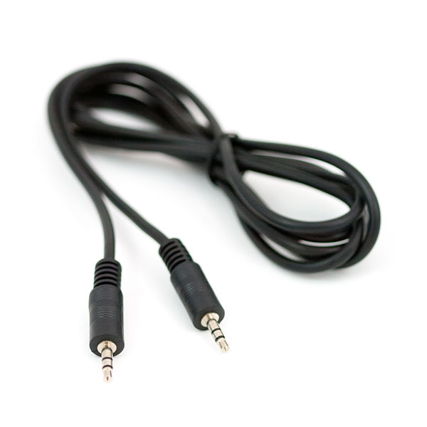
3.5mm male to 3.5mm male audio jack
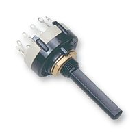
Rotary switch 3Pole 4Pos
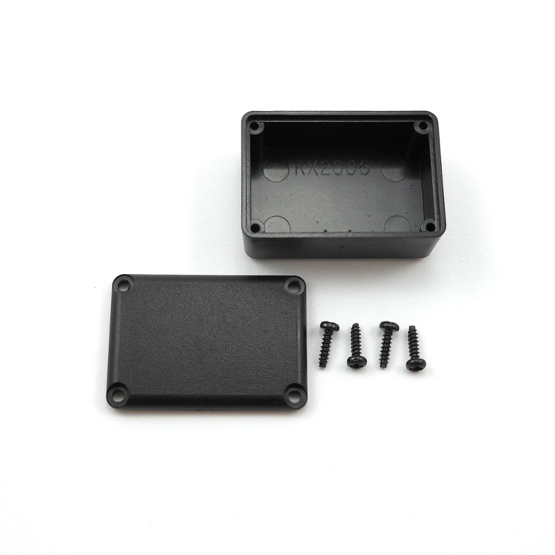
Plastic box enclosure
There won’t be much electronics theory required for this project. It will takes about 2 hours to actually build and test this project.
First, we need to know the basic of rotary switch. We can actually used a 9PDT toggle switch but will be limited to a total of 4 inputs and outputs. But, with a rotary switch we are able to get total of 5 inputs and outputs. Ofcourse more if we were to use rotary switch with more position.
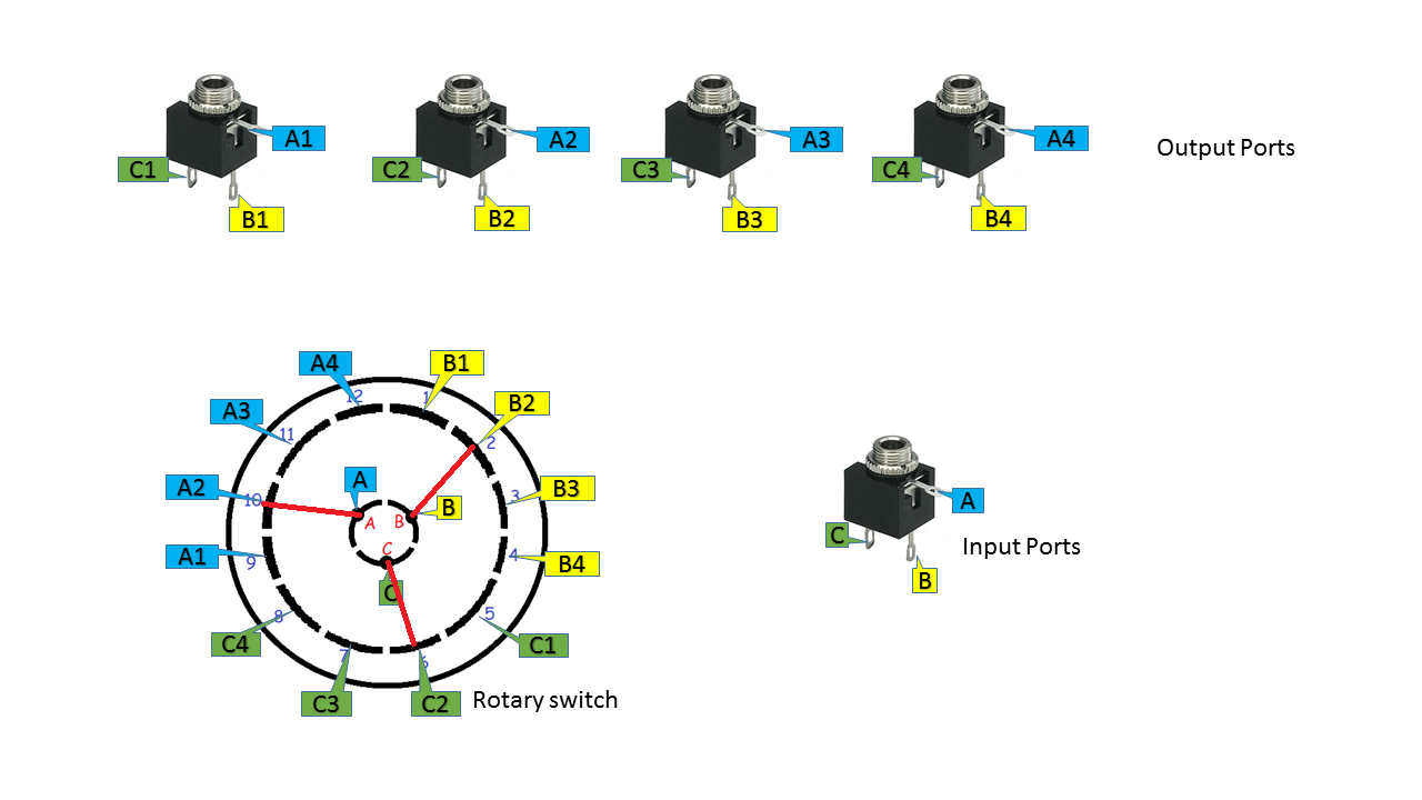
A 3 Pole rotary switch means that we have 3 connector (A,B,C) and 4 Pos meaning that 4 connector each Pole. As seen below:
- A(1,2,3,4)
- B(5,6,7,8)
- C(9,10,11,12)
By turning the switch, we will be able to select which output we want.
Rotary switch animation
As we can see, at each positon different combination is connected. 4 combination is:
- pins 1-5-9
- pins 2-6-10
- pins 3-7-11
- pins 4-8-12
Therefore, we will be using this combination later on.
Lets get started to build one.
First, determine how many output do we actually want. In my case, i’ll be going with 4 outputs. Then we need to determine the location of the outputs on the plastic box. I.ve decide to places 4 output ports on 1 side and the rotary switch with the input ports on the opposite side.
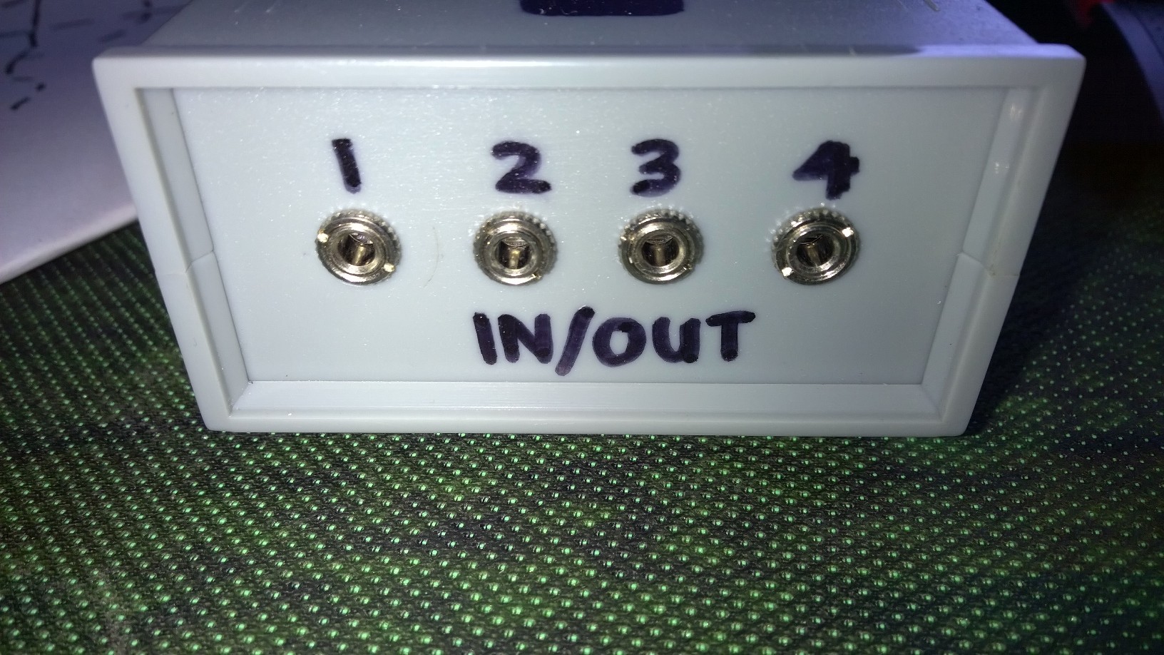
Output ports
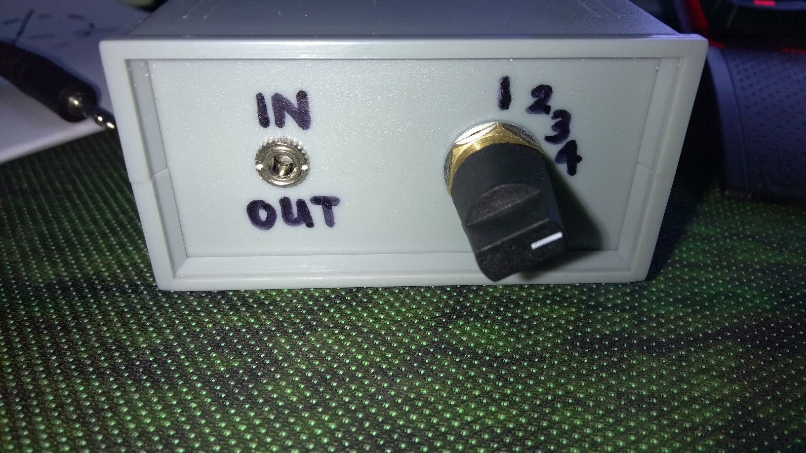
Rotary switch and input port
The reason i label both input and output ports the same is because this audio switcher can actually go both ways. Selecting multiple output ports from 1 input or selecting multiple inputs for 1 output.
I’ve started this blog after i did my project. Unfortunately, i didn’t take any picture while making this project. Therefore, completed pictures of this project will do for now. Next time, i’ll be sure to take pictures of works in progress.
Placement is done by making a guideline before drilling any hole. I measured the diameter of the audio jack, rotary switch and marks it on the box. Only then i drill it.
Next, we will take a look on its connection. As i’ve said before, this project doesn’t requires alot of electronics theory. Because this project is only redirecting the output signal position.

How to connect rotary switch, input and output ports
For this to work, each output port need to connected to either 1 of the combination we’ve seen above. Input port need to be connected to its pole as this is the only ports that will always be connected.You will want to solder all the output port to the rotary switch and rotary switch to input port according to their designation. Labelling is for easier visualization.
ATTENTION, with the wiring it might be a mess. I recommended different wire colour to ease the soldering and troubleshooting process.
Once you completely connected all the wire, now we need to check for connectivity.
Testing for connectivity
Let say we have done our soldering and the switch is in the above position(Position 2). Now, with a multimeter test for connectivity on each of the pins on the output jack relative to input jack. A2 should be connected to A, B2 connected to B and C2 connected to C. Then test the connectivity for A,B,C with the other pins on the other output pins. The other output pins shouldn’t be connected at this moment. If any of the other pins is connected, check back your wiring. Repeat this steps for the other output ports.
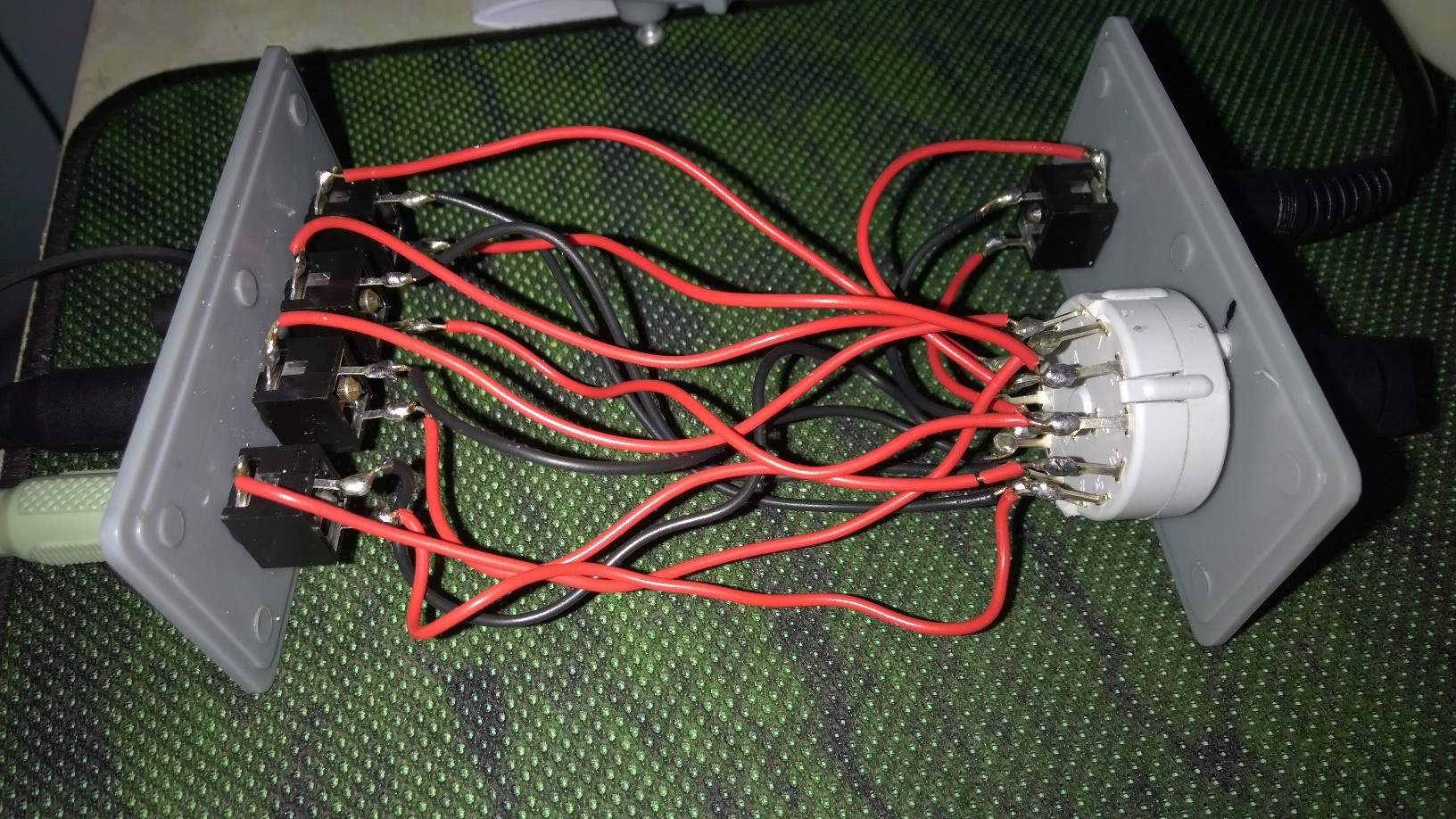
Complete wiring
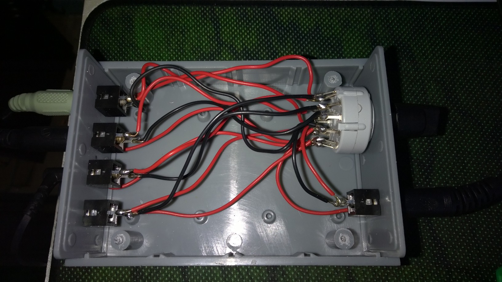
Inside the plastic box
Once you finish your troubleshooting, it now time to enclose it. Pack it nicely into your plastic box. After that, you’re good to go. Thanks for reading.
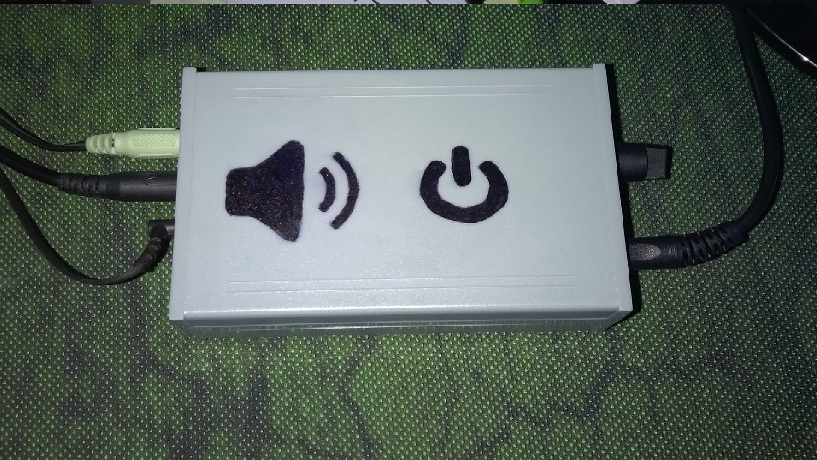
Complete Audio Switcher
